INTRODUCTION
Is the concept of electricity leaving you feeling more shocked than enlightened? Fear not, Electricity Class 10 Made Easy is your one-stop guide to conquering the exciting world of electricity and acing your CBSE 2024 exams. Do circuits and conductors cause confusion instead of clarity? We’ll break down complex concepts into easy-to-understand nuggets. Forget rote memorization – we’ll focus on building a strong foundation of understanding that will empower you to solve even the trickiest questions.
Get ready to:
- Master key concepts: Demystify terms like current, voltage, and resistance with clear explanations and visual aids.
- Unravel the mysteries of circuits: Learn how circuits work, from simple series and parallel connections to complex networks.
- Become a whiz with formulas: Understand the key formulas related to electricity and apply them confidently to solve problems.
- Ace those MCQs: Get expert tips and practice questions to help you conquer the multiple-choice questions on your exam.
- Boost your practical knowledge: Explore real-world applications of electricity and gain a deeper understanding of its significance.
Electric Current: Electricity Class 10 Made Easy
Electric charge flowing through a conductor per unit time is called electric current.
Electric current = Charge /Time
Or, I = Q/t
Imp Note-Electric current is a scalar quantity.
SI unit of current: Ampere
Definition of S.I unit of Current Or Definition of Ampere: Electricity Class 10 Made Easy
Current flowing through any cross-section of a conductor is said to be one ampere if one coulomb of charge flows through in one second.
(Conventional) direction of current:
Conventionally, the direction of current is taken as the direction of motion of positive charges through the conductor. It is opposite to that of the negatively charged electrons.
Electric circuit: Electricity Class 10 Made Easy
The closed path along which an electric current flows is called an ‘electric circuit’.
Ohm’s Law: Electricity Class 10 Made Easy
If external conditions like temperature remain constant, “the current flowing through a conductor is directly proportional to the potential difference across the ends of the conductor”.
Mathematically,
Ohm’s law is written as:
I ∝ V
V = IR
(Where R = Resistance)
V-I graph for Ohm’s law:

Resistance (R): Electricity Class 10 Made Easy
Resistance is the property of a conductor due to which it resists the flow of charges through it.
S.I. unit of resistance: Ohm (Ω).
1 ohm = 1 volt /ampere

Definition of S.I unit of Resistance or Definition of 1 Ohm:
Electricity Class 10 Made Easy
When potential difference across the ends of a conductor is 1 V and current passing through it is 1 A, then resistance of the conductor is 1 ohm.
Factors on which the Resistance of a Conductor depends: Electricity Class 10 Made Easy
Resistance of a uniform metallic conductor is-
(i) Directly proportional to the length of conductor
(ii) Inversely proportional to the area of cross-section
(iii) Directly proportional to the temperature
(iv) Depends on nature of the material
Resistivity: Electricity Class 10 Made Easy
The resistance offered by a cube of a material of side 1 m is defined as resistivity (when current flows perpendicular to its opposite faces).
(i) It’s S.I. unit is ohm-meter (Ωm).
(ii) Resistivity does not depend on length or area of cross-section of a conductor.
(iii) It changes with change in temperature.
(iv) Resistivity of alloy is generally higher than that of its constituent metals.
(v) Alloys are commonly used in electrical heating devices because they do not oxidize (burn) readily at high temperature.
(vi) Copper and aluminum are used for electrical transmission lines as they have low resistivity.
Some Important Devices: Electricity Class 10 Made Easy
Ammeter:
- It is a device to measure current in a circuit.
- It is a low resistance galvanometer.
- We always connect it in series in a circuit.
Voltmeter:
- It is a device which measures the potential difference across the ends of a conductor.
- It is a high resistance galvanometer.
- It is always connected in parallel to the circuit.
Galvanometer:
It is a device which detects current flowing through an electric circuit.
Rheostat:
A variable resistor used to regulate current without changing the source of voltage is called Rheostat.
Electric Fuse:
A safety device that protects our electrical appliances in case of short circuit or overloading is called Electric Fuse.
Important points about Fuse: Electricity Class 10 Made Easy
- Made up of pure tin or alloy of copper and tin.
- Has a low melting point.
- Current capacity is slightly higher than that of the appliance.
Resistances in series: Electricity Class 10 Made Easy
If two or more resistances are connected end to end so that same current flows through each one of them in turn, they are said to be connected in series.
If the resistances are connected in series, the total resistance or equivalent resistance is equal to the sum of the individual resistances.
Rs = Rl + R2 + R3 + ……..
Resistances in parallel: Electricity Class 10 Made Easy
If two or more resistances are connected across the same two points, they are said to be connected in parallel.
If the resistances are connected in parallel, the reciprocal of resultant resistance or the reciprocal of equivalent resistance is equal to the sum of the reciprocals of the individual resistances.
 Heating effect of current: Electricity Class 10 Made Easy
When electric current passes through a conductor, heat is produced. This is called the heating effect of current.

Joule’s law of heating: Electricity Class 10 Made Easy
Heat produced in a conductor is-
(i) directly proportional to the square of the current I through it,
(ii) directly proportional to resistance R and
(iii) directly proportional to the time t(for which current flows through the conductor).
![]()
OR,
![]()
Important Usage/ Uses / Functions/Applications of “heating effect of electric current”: Electricity Class 10 Made Easy
In the electrical heating appliances such as:
- electric iron,
- room heaters,
- water heaters
- to produce light as in an electric bulb etc.
Electric Power: Electricity Class 10 Made Easy
The rate of consumption of electric energy or the rate of doing electric work is called Electric Power :
![]()
OR
 S.I. unit of power: Watt (W)
1 Watt = 1 Volt Ampere (I VA)
Commercial unit of electric energy: Kilowatt hour (KWh)

Best Reference Book for CBSE Science 10


Definition of S.I unit of Electric Power: Electricity Class 10 Made Easy
If one ampere of current flows through it on applying a potential difference of 1 volt across its ends, then the power of the appliance is 1 watt.
1 watt = 1 joule /1 second = 1 volt × 1 ampere
1 kilowatt = 1000 W
Definition of Commercial Unit of Electrical Energy OR Definition of 1 Kilowatt hour: Electricity Class 10 Made Easy
The electrical energy consumed by an appliance of 1000 watts when used for one hour is called 1 kilowatt hour.
![]()
Efficiency of an electrical device: Electricity Class 10 Made Easy
The ratio of the output power to the input power is called efficiency of an electrical device
Efficiency= Output power/ Input power
Some Conceptual Terms Helpful in the Proper Understanding of the Chapter: Electricity Class 10 Made Easy
Resistor:
Conductor having some appreciable resistance is called a ‘resistor’.
Fuse Wire:
This is the wire which prevents the damage of various appliances by melting and breaking the circuit. It is connected in series with the live line. Its thickness determines the maximum current that can be drawn.
It is made of an alloy of aluminum, copper, iron and lead.
Semiconductors:
Semiconductors are the substances whose resistivity lie between that of an insulator and a conductor.
They are used in making integrated circuits.
Superconductors:
Superconductors are the substances that lose their resistivity at low temperature.
Superconductivity is the phenomenon of complete loss of resistivity by substances below a certain temperature.
MCQs(1 mark each): Electricity Class 10 Made Easy
1). At the time of short circuit, the electric current in the circuit:
(a) vary continuously (b) does not change (c) reduces substantially (d) increases heavily [CBSE 2020, Delhi]
Ans: (d)
2). Two bulbs(100 W and 40 W) are connected in series. What will be the current through the 40 W if current through the 100 W bulb is 1 A.
(a) 0.4 A (b) 0.6 A (c) 0.8 A (d) 1 A [CBSE 2020]
Ans : (d)
3). The minimum resistance which can be made by using five resistors of 1/ 5 Ω each ?
(a) 1 5 Ω (b) 10 Ω (c) 5 Ω (d) 1 Ω [NCERT Exemp.]
Ans : (d)
Concept- We get higher resultant resistance when resistors are connected in series. Here, the highest resistance would be 5 × 1/ 5 =1 ohm.
4). What is the minimum resistance which can be made using five resistors each of 1/5 Ω?
(a) 1 5 Ω. (b) 1 25 Ω. (c) 1 10 Ω. (d) 25 Ω. [NCERT Exemp.]
Ans : (b)
Concept- We get minimum resultant resistance when resistors are connected in parallel.


5). Which of the following represents voltage?

Ans : (a)
Concept-
Work done = Charge × Potential difference
⇒Work done = (Current × Time) × Potential Difference
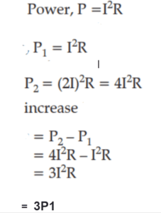
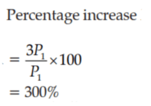
6). What will be the increase in power dissipated If the current passing through a resistor is increased by 100% (temperature remaining unchanged)?
(a) 100% (b) 200% (c) 300% (d) 400% [NCERT Exemp.]
Ans : (c)
Concept-
7). Three bulbs A, B, and C ( 40 W, 60 W, and 100 W respectively)are connected in parallel in a circuit.What is true regarding their brightness ? (a) Same for all the bulbs (b) Maximum for bulb A(c) B will be more than that of A. (d) C will be less than that of B.
[NCERT Exemp.]
Ans: (c)
Concept- A bulb with more power rating will produce more heat and light. So, the brightness of bulb B with power rating 60 W will be more than the brightness of bulb A having power rating as 40 W.
8). An electric kettle consumes 1 kW of electric power when operated at 220 V. What should be the proper rating of the fuse wire ?
(a) 1 A (b) 2 A (c) 4 A (d) 5 A [NCERT Exemp.]
Ans : (d)
Concept- Given that, power = P = 1 kW = 1000 W
Voltage = V = 220

Hence, the rating of fuse wire must be slightly greater than 4.5 A, (that is, 5 A)
Assertions and Reasons Type Questions: Electricity Class 10 Made Easy
In the given questions, Assertion (A) is followed by Reason (R). Choose the correct option-
(a) Both Assertion (A) and Reason (R) are true and R is the correct explanation of A
(b) Both assertion (A) and reason (R) are true but R is not the correct explanation of A.
(c) A is true but R is false.
(d) A is false but R is true.
1). Assertion (A): Silver metal is not used for making electric wires.
Reason (R): Silver is a bad conductor of electricity.
Ans. Correct option : C
Concept- Although Silver is a good conductor of electricity, it is very expensive.
2). Assertion (A): Copper is often used to make electric wires.
Reason (R): Copper has very low electrical resistance.
Ans. Correct option : (a)
Concept- Copper has low electrical resistance .So,it is a good electric conductor.
3). Assertion (A): In electrical heating devices like electric iron and heater, alloys are commonly used.
Reason (R): The alloys have low melting points than their constituent metals and resistivity of an alloy is generally higher than that of its constituent metals
Ans. Correct option : (c)
Concept- They have light resistivity and high melting point as compared to their constituent metals.
4). Assertion (A): The point of lowest potential is the positive terminal of the battery in a simple circuit
Reason (R): As the current flows in from the positive to the negative terminal, it flows towards the point of the lower potential.
Ans. Correct option : (d)
Concept- The point of lowest potential is the negative terminal of the battery. Flow of current takes place from higher potential to lower potential.
5). Assertion (A): An electric bulb has a two pin connection whereas electric appliances with a metallic body have three connections(pins)
Reason (R):Heating of connecting wires is reduced by three pin connection.
Ans. Correct option : (C)
Concept- The extra charge flowing through the metallic body is passed to earth and avoids shocks. Nothing is concerned with reducing of the heating of connecting wires.
6). Assertion (A): When the switch is ON, the electric bulbs glow immediately
Reason (R): The drift velocity of electrons in a metallic wire is very high.
Ans. Correct option : (a)
Concept- There are some free electrons in a a conductor.
Case Study Based Questions: Electricity Class 10 Made Easy
(Answers have been given at the end of the question for your better revision)
1). Observe the graph and answer these questions –
In the given figure, we have a V-I graph for a conductor.

a). Which of the following law justify the above graph:
(i) Faraday’s Law
(ii) Ohm’s Law
(iii) FaradLaw
(iv) Joule’s Law
b). Resistance of a conductor depends on:
(i) length of conductor
(ii) area of cross-section
(iii) temperature
(iv) all of the above
c). What do you infer from this graph ?

d). Ohm is the SI unit of:
(i) Potential difference
(ii) Resistance
(iii) Current
(iv) Resistivity
e). Name the physical quantity represented by the slope of this graph
(i) Current
(ii) Resistance
(iii) Potential difference
(iv) None of the above
Ans.
(a) (ii) Ohm’s Law
(b) (iv) all of the above
(c) (iii) V ∝ I
(d) (ii) Resistance
(e) (ii) Resistance
2). In the given circuit, connect a nichrome wire of length ‘L’ between points X and Y and note the ammeter reading Answer any four questions from (a) to (e)-

(a). If we double the area of the cross section without changing the length in the above experiment, the changes that are observed in the ammeter reading
(i) Ammeter reading will increase
(ii) Ammeter reading will decrease
(iii) Will decrease half
(iv) No change in ammeter reading
(b). When nichrome and copper wire of same length and same radius are connected in series and current I is passed through them. Which wire gets heated up more?
(i) Nichrome (ii) Copper
(iii) Both heat up at the same temperature (iv) None
(c). The instrument used to measure current is ____________.
(i) Galvanometer (ii) Voltmeter (iii) Ammeter (iv) manometer
(d). When this experiment is repeated by inserting another nichrome wire of the same thickness but twice the length (2L), what changes are observed in the ammeter reading ?
(i) Ammeter reading will increase
(ii) Ammeter reading will decrease
(iii) Will show double the increase
(iv) No change in ammeter reading
(e). In a circuit two resistors of 5 Ω and 10 Ω are connected in series. Ratio of the currents passing through the two resistors.
(i) 1 : 2 (ii) 1: 3 (iii) 2: 1 (iv) 1:1
Ans.
(a) (ii) The ammeter reading will increase (becomes two times).
(Concept-There will be an increase in the ammeter reading(it will become double). As area increases, resistance decreases and so current increases. )
(b) (i) nichrome wire
(c) (iii) Ammeter.
(d) (i) ammeter reading will decrease (becomes half)
(Concept- The ammeter reading will decrease (becomes half). When length increases, resistance of the circuit also increases. Consequently, current decreases. )
(e) (iv) 1:1
(Concept-In a series connection of resistors, the same current passes through all the resistors. Hence, current will be the same. Hence, Ratio of the currents =1: 1)
3). Study the circuit shown in which three identical bulbs B1, B2 and B3 are connected in parallel with a battery of 4.5 V. Answer the following questions-

(a) Readings shown by ammeter A when all the bulbs glow simultaneously, the wattage of each bulb being 1.5 W.
(i) 1.0A (ii) 2A (iii) 1.5W (iv) None of the above
b) The equivalent resistance of the circuit will be
(i) 1.0Ω (ii) 4.5Ω
(iii) 1.5Ω (iv) 2.0Ω
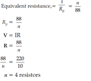
(c) No. of resistors of 88 W to be connected in parallel so that 10 A current flows at voltage of 220 V
(i) 2 resistors (ii) 1 resistors (iii) 3 resistors (iv) 4 resistors
(d) What will happen to the other two bulbs if the bulb B3 gets fused ?
(i) They will also stop glowing (ii) Other bulbs will glow with same brightness (iii) They will glow with low brightness (iv) They glow with more brightness
(e) Find the statement which does not justify parallel connection:
(i) Each component will have the same voltage
(ii) Resultant resistance will be lower than that of single component
(iii) Automobile headlight is connected in parallel
(iv) A single path for the flow of electrons/ charge
Ans.
(a) (i) 1.0 A
(Concept-
As the bulbs are in parallel,
Total wattage/Power= 1.5+1.5+1.5 = 4.5 W
Now.
I = P/V = 4. 5/ 4. 5 = 1A)
(b) (ii) 4.5Ω
(Concept-
Ammeter reading = 1.0A, V = 4.5V
R = V/I = 4.5/1= 4.5 Ω
(c) (iv) 4 resistors)
Concept-
 (d) (ii)
Concept-
Other bulbs will glow with same brightness.
(e) (iv)
(Concept- There is a path of flow of electron change through each resistor. So there are several paths.)
Short Answer: Electricity Class 10 Made Easy
Long Answer: Electricity Class 10 Made Easy
Numerical: Electricity Class 10 Made Easy
1)An electric circuit (shown here) has been made by a student to measure the current through two lamps.
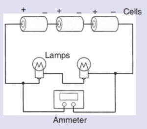
(a) Say whether the lamps are in series or parallel?
(b) Can you check the mistake in this circuit?
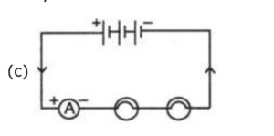
(c) If you find a mistake, draw a circuit diagram to show the correct way to connect the circuit using the proper circuit symbols.
Answer
(a) The lamps are connected in series. In a series circuit, All the devices must be functioning for the circuit to become complete.
(b) An ammeter is always connected in series.
But they have connected the Ammeter in parallel with the lamps. This is the mistake we need to correct.
2) 8 Ampere current flows through an electric heater connected to the 230 V mains supply.
(a) Find the amount of charge flowing around the circuit every second ?
(b) Find the energy transferred to the heater every second ?
Solution-
(a) Here,
Potential difference = 230 V
Current(I) = 8A
Time(t) = 1 Second
Q=I X t = 8x 1= 8 C
So in each second the amount of charge flowing in the circuit is 8 C.
(b) As we know that the work done is equal to the amount of energy transferred in a circuit. Voltage/Electric potential difference is equal to the work done per unit charge in moving the charge from one point to another point.


Work done = 230 x 8 = 1840 J
Energy transferred = 1840 j
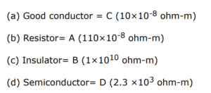
3).

Answer-
4). What happens to the resistance of a wire if-
(i) its length is tripled ?
(ii) its diameter is tripled ?
(iii) its material is replaced by the one whose resistivity is three times as compared to the former material
Answer-
(i) Its resistance also becomes three times when the length is tripled because the resistance of a wire is directly proportional to its length and
(ii) Its resistance becomes one ninth of the initial resistance if the diameter get tripled because resistance is inversely proportional to the area of cross section or inversely proportional to the square of the diameter).
(iii) If the material is replaced by the one having tripled resistivity, its resistance becomes three times.
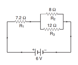
5). In the given diagram,
Find (i) Equivalent resistance of the circuit,
(ii) current flowing in the circuit, and (iii) Voltage/the potential difference across the resistance R1
Solution-
i). Let us first calculate the resultant resistance R of R2 and R3 which are connected in parallel.
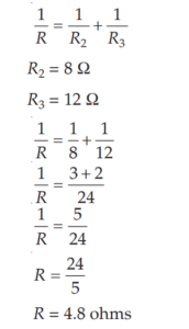
We can now draw another circuit diagram for this problem by showing a single resistance of 4.8 ohms in place of two parallel resistances.
From this diagram(given below), It is clear that we have two resistances of 7.2 ohms and 4.8 ohms which are connected in series.
So, Total resistance = 7.2 + 4.8 = 12 ohms

Thus, the total resistance of the circuit is 12 ohms
(ii) Total potential difference, V = 6 volts
Total current, I = ? and Total resistance, R = 12 ohms (Calculated above)
Applying Ohm’s law, we get
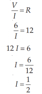
So, Total current, I = 0.5 ampere (or 0.5 A)
(iii)
Now,Potential difference across R1= ?
Current through R1 = 0.5 ampere
And, Resistance of R1 = 7.2 ohms
Applying Ohm’s law, we get :
Considering R1 as R,
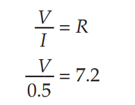
Or, V = 7.2 × 0.5
Or, V = 3.6 volts
Thus, the potential difference across the ends of the resistance R1 is 3.6 volts
6). How many of these resistors should be connected in parallel to a resistor having a resistance of 176 ohms so that their combination can draw a current of 5 amperes from a supply line of 220 volt ?
Answer
According to Ohms Law,
V= IR
(Where V= Voltage/Potential Difference, I= Current R=Resistance)
According to Question,
V= 220V, I= 5A
∴ Total Resistance,
R= V/I = 220/5
= 44 Ohm
7). An electric heater which is connected to a 220 V supply line has two resistance coils A and B of 24 resistance each. In what way can these coils can be used separately (one at a time), in series or in parallel?
Calculate the current drawn when :
(a) coil A is the only resistor which is used.
(b A and B are used in series.
(c) A and B are used in parallel.
Answer
(a) Only one coil is used, which is coil A
V= IR
220= 24I
I = 220/ 24
I = 9.2 Ampere(A)
(b)If the coils are used in series
Total resistance R= RA +RB = 24+24 = 48 ohms
I = V/R = 220/48
I = 4.58 A
(c) If the coils are used in parallel.
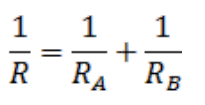

R=12 ohms
I = V/R = 220/12 =18.33A
8). A 4 Ohm coil and a 2 Ohm coil are connected in parallel. What is their combined resistance ?
If a current of 3 A passes through the coils.
What amount of current will pass through the 2 coils ?
Solution-
Here, Resistors (Coils) 4 ohm and 2 ohms are connected in parallel,
Hence,

Total current =3 A (given)
Potential difference, V= IR=3×4/3=4V
Now current through 2Ω coil, I= V/R= V/2 =4/2 = 2A
FAQs: Electricity Class 10 Made Easy
1). I’m scared of electricity! Is it safe to learn about it?
While electricity demands respect, there’s no need to fear it. Understanding its principles makes you a safer user. This blog post focuses on theoretical concepts and doesn’t involve any practical experiments. Remember, knowledge is power, and understanding electricity empowers you to use it safely and responsibly.
2). I struggle with physics. Will this blog help me understand electricity?
This blog uses simple language, real-life examples, and relatable analogies to break down complex concepts into bite-sized pieces. Even if you find physics challenging, this blog is designed to make the journey of learning electricity enjoyable and approachable.
3). What are the most important topics I should focus on for the CBSE Class 10 Electricity exam?
This blog covers all the crucial topics outlined in the CBSE Class 10 syllabus, including electric charges, circuits, Ohm’s law, power, and magnetism. By following along, you’ll gain a solid foundation in these key areas. However, it’s always wise to refer to your textbook and consult your teacher for specific exam tips and weightage.
4). Are there any tips or tricks to remember formulas easily?
Remembering formulas can be tricky, but there are ways to make it easier. This blog uses mnemonic devices, diagrams, and real-world applications to help you connect the formulas to concepts, making them more meaningful and easier to recall.
5). What are some common mistakes students make in understanding electricity?
This blog highlights some common misconceptions and clarifies them with simple explanations. By being aware of these potential pitfalls, you can avoid making the same mistakes and build a strong understanding of electrical concepts.
6). How can I practice what I learn and test my understanding?
This blog includes practice questions and interactive quizzes at the end of each section to help you apply your knowledge and assess your understanding. You can also find plenty of additional practice questions and sample papers online and in your textbooks.
7). What are some real-world applications of electricity that I can explore?
Electricity plays a vital role in our daily lives. This blog points out connections between the concepts you learn and their applications in everyday appliances, gadgets, and even the human body! Understanding these connections makes learning more engaging and reinforces your grasp of the concepts.
Conclusion: Electricity Class 10 Made Easy
Remember, the key to success is not just memorizing facts but truly understanding the underlying principles. This blog serves as a steppingstone to ignite your curiosity and guide you on your journey to mastering electricity!
ALSO READ-
https://pcmconceptclear.com/best-book-for-science-class-10-cbse/
https://pcmconceptclear.com/science-class-10-control-and-coordination/
https://pcmconceptclear.com/science-class-10-light-reflection-and-refraction/
https://pcmconceptclear.com/science-class-10-life-processes/
https://pcmconceptclear.com/science-class-10-acids-bases-and-salts/
https://pcmconceptclear.com/class-10-chemical-reactions-and-equations/
https://pcmconceptclear.com/acids-bases-salts-most-imp-qa
https://pcmconceptclear.com/chemical-reactions-and-equations-class-10-science
https://pcmconceptclear.com/world-of-dimensional-formula-class11/

 Heating effect of current:
8 thoughts on “Spark Your Knowledge! Electricity Class 10 Made Easy (2025-26)”